Coco Gauff is safely into the 2025 Wuhan Open quarter-finals.
The USA tennis titan continued her solid form in the People’s Republic of China, as she beat home hope Zhang Shuai 6-3, 6-2 in the round of 16 on Thursday (9 October).
It’s a quick…

Coco Gauff is safely into the 2025 Wuhan Open quarter-finals.
The USA tennis titan continued her solid form in the People’s Republic of China, as she beat home hope Zhang Shuai 6-3, 6-2 in the round of 16 on Thursday (9 October).
It’s a quick…

Samsung is expected to launch its Project Moohan XR headset as soon as this month, but a leak shared by Android Headlines may give us an early look at its specs. The leak suggests that the Android-based headset will offer a 4K micro-OLED display…

Chinese tech giant Huawei has launched an updated version of its Watch Ultimate smartwatch-style dive computer, which now features underwater diver-diver…
Figure 4(a) illustrates the mesh domain of the present CFD model. This system uses an unstructured mesh due to the existence of KSM in the RO. For mesh independence analysis, Fig. 4(b) illustrates the mass transfer coefficient as a function of the number of elements. According to the results, after 300,000 elements, the variation in the mass transfer coefficient is not significant; thus, this mesh is used for calculations.
For validation of mass transfer in the RO, Fig. 4(c) presents a comparison of mass transfer from this study and the study by Li et al.26 as a function of inlet velocity. The inlet concentration of salt in the RO is 13 mol/m2, and the feed pressure is 13.6 bar. According to the results, the average relative error between the present model and the data from Li et al. is less than 5%, indicating good agreement.
To the best of our knowledge, no previous study has investigated RO with KSM. Therefore, to validate the flow characteristics of an RO system with a spacer, the present study utilizes the data from Kavianipour et al.19, who examined a submerged spacer in an RO system. Figure 4(d) presents a comparison of the pressure drop between the current study and the data reported by Kavianipour et al. across different Reynolds numbers. The results indicate that the average relative error between the present model and the data from Kavianipour et al. is less than 2%, demonstrating strong agreement.
Mesh analyzing: (a) The mesh domain of the present CFD model, (b) Mass transfer coefficient, (c) A comparison of mass transfer from this study and the study by Li et al.26, (d) A comparison of the pressure drops between the current study and the data reported by Kavianipour et al.19.
Figure 5 illustrates the velocity and concentration distributions in the RO feed channel at Re = 300. The subfigures are: (a) velocity distribution in ROKSM, showing enhanced mixing due to helical elements; (b) velocity distribution in standard RO, with more laminar flow and boundary layer buildup; (c) concentration distribution in ROKSM, demonstrating reduced wall concentration (indicating lower CP); and (d) concentration distribution in standard RO, with higher wall concentration and pronounced CP layer. These profiles confirm that KSM disrupts the boundary layer, reducing CP factor (CPF) from 1.038 in standard RO to 1.015 in ROKSM, leading to improved mass transfer.
In the velocity distributions (Fig. 3a and b), the ROKSM process (Fig. 5a) exhibits a more complex and varied color pattern, indicating enhanced mixing induced by the KSM elements. The static mixers disrupt the laminar flow, creating regions of higher velocity and turbulence, which are absent in the standard RO process (Fig. 5(b)). In Fig. 5(b), the standard RO shows a predominantly uniform blue-green pattern, suggesting a more consistent but lower velocity profile, typical of laminar flow without mixing elements. This contrast highlights KSM’s role in promoting a more dynamic flow, which can reduce stagnant zones and enhance mass transfer.
The concentration distributions (Figs. 5(c) and 5(d)) further elucidate the effect of KSM on solute behavior. In the ROKSM process (Fig. 5(c)), the concentration varies between 13 and 16 mol/m³, with a more uniform distribution across the channel, indicating effective mixing that mitigates solute accumulation near the membrane surface. The presence of KSM elements disrupts the concentration boundary layer, preventing the pronounced red zones (higher concentrations) seen in the standard RO process (Fig. 5(d)), where concentrations reach up to 16 mol/m³ near the outlet. The standard RO shows a clear gradient, with increasing concentration along the flow path, reflecting severe concentration polarization due to the lack of mixing. This qualitative difference supports of reduction in concentration polarization with ROKSM, as the uniform concentration profile reduces the risk of fouling and enhances membrane performance.
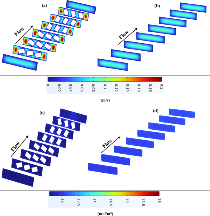
(a) Velocity distribution in ROKSM; (b) Velocity in standard RO; (c) Concentration distribution in ROKSM (lower wall CP); (d) Concentration in standard RO (higher wall CP).
As mentioned, Fig. 5 shows velocity distributions in (a) ROKSM and (b) standard RO, and concentration distributions in (c) ROKSM and (d) standard RO, confirming reduced CP in ROKSM.
Figure 6 compares the Sherwood number, pressure drop, and concentration distribution for different Reynolds numbers (Re) and the number of rows of the KSM. Figure 6(a) shows that the Sherwood number increases with an increase in the Reynolds number. The condition with three rows of KSM showed the highest Sherwood number, indicating better mass transfer performance compared to one row of KSM and without KSM. According to Fig. 6(a), the Sherwood number (Sh) is significantly higher in the ROKSM system compared to the standard RO process, especially with three rows of KSM. At Re = 300, the Sherwood number for ROKSM with three rows is approximately 1.6 times of the standard RO process. Even with one row of KSM, the Sherwood number is 1.3 times of the standard RO process. Figure 6(a) shows that the ROKSM system enhances mass transfer efficiency by up to significantly compared to the standard RO process, with three rows of KSM providing the best performance. Figure 6(b) represents that the pressure drop increased with an increase in the Reynolds number. The condition with three rows of KSM showed the highest pressure drop, indicating higher resistance to flow compared to one row of KSM and without KSM. At Re = 300, the pressure drop for ROKSM with three rows is approximately 4.7 times of the standard RO process. With one row of KSM, the pressure drop is 1.5 times of the standard RO process. While ROKSM improves mass transfer, it increases the pressure drop which is a trade-off that must be managed. Figure 6(c) depicts the concentration profile along the RO system enhanced with KSM (ROKSM) at Re of 100, 200, and 300, while Fig. 6(d) shows the same for a standard RO system without KSM.
The main findings underscore the effectiveness of KSM in improving RO performance. ROKSM reduces concentration polarization as evidenced by the lower outlet concentration. Higher Re values improve mixing in ROKSM, smoothing the concentration profile and reducing peaks, while in standard RO, they exacerbate polarization due to the lack of mixing. However, this comes with a higher pressure drop, a trade-off that requires further optimization. The lower osmotic pressure in ROKSM enhances the net driving force for water flux.
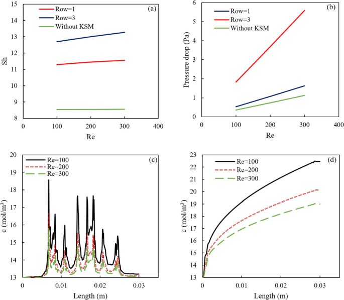
Representing the relationship between: (a) the Sh number and the Reynolds number, (b) the pressure drops and the Reynolds number, and (c) and (d) the concentration along the length of the system with different Reynolds numbers.
The incorporation of KSM in the ROKSM configuration enhances mass transfer by disrupting the laminar flow typical of standard RO systems, as evidenced by the complex velocity patterns in Fig. 5(a). This disruption creates localized turbulence, which reduces the concentration boundary layer near the membrane surface, lowering concentration polarization and increasing the Sherwood number to (Fig. 6(a)). However, the KSM’s twisted geometry increases flow resistance, leading to a pressure drop approximately 4.7 times higher than that of standard RO at Re = 300 (Fig. 6(b)). This trade-off arises because the enhanced mixing requires additional energy to overcome the increased frictional losses within the feed channel. The 30-degree twist angle optimizes mixing by maximizing flow disruption, but it also results in the highest pressure drop, necessitating a careful balance between mass transfer gains and energy costs.
The ROKSM system increases water flux by 23%, from 13 L/m2 h for standard RO to 16 L/m²h at Re = 300, driven by reduced concentration polarization due to enhanced mixing by Kenics static mixers. The CFD model (Sect. 4) shows this through concentration profiles, with ROKSM exhibiting a uniform distribution ranging from 13 to 16 mol/m³, compared to standard RO’s pronounced gradient reaching 22 mol/m2 at the outlet wall. The outlet wall concentration is 13.5 mol/m³ for ROKSM and 16 mol/m2 for standard RO, with a bulk concentration of 13 mol/m2 (Table 3).
This reduction in wall concentration lowers the osmotic pressure, which, per Eq. (1), increases water flux. The hydraulic permeability is 2.74 m/h/bar, and the feed pressure is assumed at 60 bar, with a permeate pressure of 1 bar. The salt diffusion coefficient is 1.6 × 10⁻³m²/s, and the channel height is 1 mm (Table 3). The Sherwood number for ROKSM is 13.6, compared to 8.5 for standard RO, indicating enhanced mass transfer that reduces solute buildup at the membrane surface. The CFD model, validated with less than 5% error, confirms that ROKSM’s higher Sherwood number and lower wall concentration directly contribute to the 23% flux increase, as visualized in Fig. 5(c) compared to Fig. 5(d).
Sherwood number is an indicator of mass transfer performance. Higher Sherwood numbers represent better mass transfer efficiency. According to Fig. 7(a), the Sherwood number increased with the Reynolds number for all conditions. The KSM at a 30-degree angle showed the highest Sherwood number, indicating the best mass transfer efficiency. The KSM at a 90-degree angle showed a lower Sherwood number compared to the 30-degree angle but still higher than without KSM.
Figure 7(b) shows that the pressure drop increased with the Reynolds number for all conditions. The KSM at a 30-degree angle showed the highest pressure drop, indicating the greatest resistance to flow. The KSM at a 90-degree angle represented a lower pressure drop compared to the 30-degree angle but higher than without KSM.
Figure 7 shows that the KSM at a 30-degree angle provides the best mass transfer efficiency, as indicated by the highest Sherwood number. This suggests that the 30-degree angle is more effective at promoting mixing and enhancing mass transfer. In terms of flow resistance, the KSM at a 30-degree angle also results in the highest pressure drop, indicating increased resistance to flow. This is a trade-off that must be considered when optimizing the process.
The angle of the KSM has a significant impact on both mass transfer efficiency and flow resistance. While a 30-degree angle provides the best mass transfer, it also increases the pressure drop. Therefore, the angle should be optimized based on the specific requirements of the process, balancing mass transfer efficiency and flow resistance. Overall, the analysis highlights the importance of the angle of the KSM in optimizing the RO process. Adjusting the angle can significantly impact the performance, and careful consideration is needed to achieve the desired balance between efficiency and resistance. Figure 8 represents the velocity and concentration distribution for different 30- and 90-degrees positions of the mixers.
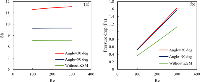
Relationships between: (a) Sh number and Reynolds number, and (b) pressure drop and Reynolds number, in a standard RO system and ROKSM with different angles.
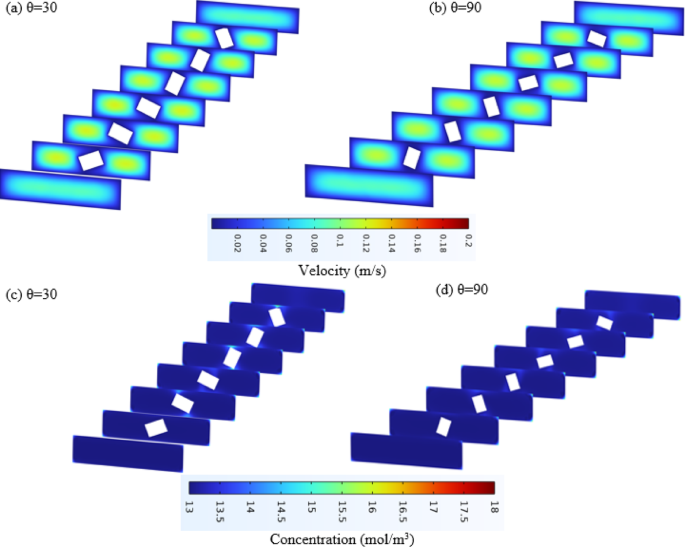
Representing the velocity and concentration for two different 30- and 90-degree positions of the mixer.
In this section, the effect of integrating ROKSM with tidal energy is investigated (ROTE-KSM). First, the range of power that can be harnessed from tidal energy is determined. This power is then utilized to drive a feed pump. The outlet pressure of the pump is considered the feed flow pressure, which is then supplied to the ROTE-KSM system. Table 4 represents the several tidal stream generator sites according to their capacity and scale. Figure 6 illustrates the outlet pressure of the pump as a function of different tidal power sites, considering a flow rate range between 300 and 1000 m³/h. This figure is generated using Aspen Plus V12.
As expected, an increase in flow rate results in a decrease in outlet pressure. For a power input of 600 kW, the outlet pressure ranges between 55 and 17 bar. At 1000 kW, the pressure varies from 91 to 28 bar, while for 1700 kPa, it ranges between 153 and 46 bar. In all three cases, the generated pressure is sufficient for RO applications. However, it is important to note that RO membranes have an upper-pressure limit due to structural constraints. With this renewable energy source, the primary concern is the minimum pressure required to effectively utilize tidal energy for pressure generation and overcome the osmotic pressure of the feed flow. Some studies consider the maximum feed pressure to be below 80 bar. Therefore, in this study, we investigate feed pressures ranging between 17 and 80 bar, which falls within the pressure range available from tidal power. The minimum and maximum pressures within this range are presented in Fig. 9.
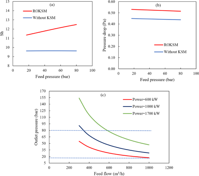
(a) Effect of feed pressure on Sherwood number for both RO and ROKSM systems, (b) effect of feed pressure on pressure drop for RO and ROKSM systems, and (c) effect of feed flow rate on outlet pressure at different pump powers.
To clarify the integration of tidal energy with the ROKSM system, we define an operating condition for the primary CFD analysis at Re = 300, where key results are reported (Sherwood number of 13.6, 23% flux increase from 13 to 16 m/h). For a 10,000 m2/day (3.65 million m³/year) desalination plant, we select a feed flow rate of 500 m2/h (within 300–1000 m2/h, Sect. 5.4) and a feed pressure of 60 bar (within 17–80 bar, Table 3), typical for seawater RO with an inlet salinity of 13 mol/m2 (Table 3). The ROKSM system’s 4.7-fold higher pressure drop (Fig. 4b) requires a total pressure of ~ 63.5 bar (60 bar feed + 3.5 bar drop), compared to ~ 61 bar for standard RO (60 bar + 1 bar drop). The pump power (P), calculated as:
$$:P=frac{Q.varDelta:P}{eta:}$$
(12)
With flow of Q = 500 m3/h (0.1389 m2/s) and efficiency of η = 0.85, is ~ 1000 kW for ROKSM and ~ 990 kW for standard RO, well within the 600–1700 kW provided by tidal power sites (Table 4), as shown in Fig. 6c.
The table below summarizes operational process parameters for the feed, permeate, and brine streams in both systems at Re = 300, providing insight into the desalination process. Inlet and outlet pressures, temperatures, and flow rates are based on the CFD model, with permeate pressure assumed at 1 bar (ambient) and temperature at 25 °C (isothermal model). The brine flow rate is estimated assuming a 40% recovery ratio (typical for seawater RO), where permeate flow is 40% of the feed flow, and brine flow is the remainder.
The ROTE-KSM system integrates tidal energy with the KSM-enhanced RO process to achieve a sustainable and efficient desalination solution. The CFD-based analysis evaluates the mass transfer performance of the ROKSM system across a range of feed pressures (17–80 bar), which aligns with the pressure output from tidal stream generators (Table 4; Fig. 6). This range accounts for the time-dependent nature of tidal energy, which varies with tidal cycles approximately every 12 h22,23. To address the reviewer’s concern about the unrealistic operation of RO at varying pressures, we incorporate energy storage and pressure regulation mechanisms to ensure stable RO operation.
Tidal stream generators harness kinetic energy from tidal currents, producing power outputs ranging from 600 to 1700 kW at sites such as Bluemull Sound (Scotland), Uldolmok (South Korea), and Zhejiang (China) (Table 4). Using Aspen Plus V12, we modeled the outlet pressure of the feed pump as a function of flow rate (300–1000 m³/h), yielding pressures of 17–153 bar (Fig. 6). To mitigate the variability in tidal energy output, the system employs energy storage solutions, such as batteries or pumped storage hydropower, to store excess energy during peak tidal flows and release it during low tides. Additionally, variable frequency drives (VFDs) on high-pressure pumps regulate feed pressure to maintain optimal RO performance, ensuring that pressures remain within the operational range of 50–80 bar required for seawater desalination. This approach ensures consistent operation despite tidal fluctuations.
The CFD model evaluates the ROKSM system’s performance across a range of feed pressures (17–80 bar) to account for potential variations in tidal energy supply. The model assumes a feed pressure of 60 bar as a baseline (Sect. 5.3), with a hydraulic permeability of 2.74 L/m²h/bar and a salt diffusion coefficient of 1.6 × 10⁻⁹ m²/s (Table 3). The results show that the ROKSM configuration with three rows of KSM at a 30° twist angle achieves a Sherwood number of 13.6 and a 23% increase in water flux (from 13 to 16 L/m²h) at Re = 300, even under varying feed pressures (Fig. 6). The model’s robustness across this pressure range demonstrates the system’s adaptability to tidal energy fluctuations, ensuring reliable performance.
By combining tidal energy with KSM, the ROTE-KSM system achieves a 1.6-fold increase in the Sherwood number (from 8.5 to 13.6) and a 23% increase in water flux, reducing concentration polarization (Sect. 5.6). The use of renewable tidal energy eliminates reliance on grid electricity, lowering carbon emissions to 2.4 kg/m³ (Sect. 5.6). The higher pressure drop in ROKSM (4.7 times that of standard RO at Re = 300, Fig. 4b) is mitigated by Energy Recovery Devices (ERDs), which recover up to 95% of the energy from the high-pressure brine stream (Sect. 2.2), resulting in a net specific energy consumption (SEC) of 2.2–2.5 kWh/m³, comparable to or lower than standard RO (2.5–3 kWh/m³). The integration of energy storage and pressure regulation ensures that the system maintains optimal performance, making tidal energy a practical and sustainable power source for RO desalination.
The integration of KSM in the ROKSM configuration enhances mass transfer, achieving a 1.6-fold increase in the Sherwood number and a 23% increase in water flux (from 13 to 16 m/h), as shown in Fig. 6(a). However, this improvement incurs a higher pressure drop, with ROKSM with three rows exhibiting a pressure drop 4.7 times that of standard RO at Re = 300 (Fig. 6b). To evaluate the sustainability of the ROKSM system, the energy penalty of the increased pressure drop against the energy savings from improved water flux was analyzed.
The energy required by the feed pumps is proportional to the pressure drop and flow rate. For ROKSM with three rows, the 4.7-fold increase in pressure drop translates to an estimated additional energy demand of around 0.5–1 kWh/m³ compared to standard RO (according to try and error experience of real plants), assuming a baseline specific energy consumption (SEC) of 2.5 kWh/m³ for seawater RO. However, the 23% increase in water flux reduces the volume of water that must be processed to achieve the same freshwater output, lowering the effective SEC by approximately 0.4–0.6 kWh/m³. Additionally, the use of Energy Recovery Devices (ERDs), which recover up to 95% of the energy from the high-pressure brine stream, further mitigates the energy penalty30.
When powered by tidal energy (600–1700 kW, Table 4), the ROKSM system leverages a renewable energy source with a low operational cost and reduced carbon emissions (2.49 kg/m³)31. Preliminary calculations indicate that the net SEC for ROKSM remains comparable to or lower than that of standard RO (2–2.5 kWh/m³ vs. 2.5–3 kWh/m³), ensuring net energy savings. The integration with tidal energy eliminates reliance on grid electricity, enhancing the system’s sustainability. To optimize this trade-off, future work will explore intermediate KSM configurations (two rows or adjusted twist angles) to balance mass transfer efficiency and pressure drop, ensuring maximum energy efficiency for scalable applications.
While Sh increases 1.6-fold, the 4.7-fold ΔP imposes a significant energy penalty. Frictional losses in the feed channel (~ 20% of ΔP) are unrecoverable by ERDs, which only reclaim brine energy (efficiency 95%32. Net SEC rises by ~ 1.2 kWh/m2, tempering flux gains to 15% effective according to Eq. (13):
$${text{SEC}}_{{{text{net}}}} = {text{ }}left( {Delta {text{P}}_{{{text{feed}}}} /{text{ }}eta _{{{text{pump}}}} } right){text{ }} + {text{ SEC}}_{{{text{other}}}} – {text{ }}left( {Delta {text{P}}_{{{text{brine}}}} *{text{ }}eta _{{{text{ERD}}}} } right)~~~~$$
(13)
This highlights the need for optimized KSM designs to balance benefits.
To evaluate the economic viability of the ROKSM system, we estimate the Levelized Cost of Water (LCOW), calculated by Eq. 4, for a 10,000 m³/day plant and compare it to a conventional RO system33. The ROKSM system achieves a 23% higher water flux (16 m/h vs. 13 m/h), reducing the required membrane area by 18.75% (from 32,051 m² to 26,042 m²). This lowers capital costs for membrane modules, despite higher costs for tidal energy infrastructure and pumps to handle the 4.7-fold pressure drop increase (Fig. 6b).
$$:LCOWleft(frac{USD}{{m}^{3}}right)=frac{Total:Annualized:Cost:(USD/year)}{Annual:Water:Production:({m}^{3}/year)}$$
(14)
where Total Annualized Cost includes annualized capital expenditure (CapEx) and operational expenditure (OpEx).
ROKSM achieves 16 m/h vs. 13 m/h for standard RO (23% increase). Additionally, a specific energy consumption (SEC) of 2–3 kWh/m³ for standard RO was estimated in the previous section. For ROKSM, the 4.7-fold pressure drop increase (Fig. 6b) adds ~ 0.5–1 kWh/m³, but the 23% flux increase and ERDs (95% recovery) yield an estimated SEC of 2–2.5 kWh/m³. for operational cost, ROKSM’s cost is around 0.5582 $/m³, likely including tidal energy’s lower cost compared to grid electricity (~ 0.1–0.15 $/kWh for grid vs. ~0.05 $/kWh for tidal, assumed based on renewable energy trends).
In terms of plant capacity, a medium-scale RO plant producing 10,000 m³/day (3.65 million m³/year) was assumed, typical for seawater desalination (aligned with flow rates of 300–1000 m³/h)34. For membrane Area, the 23% flux increase reduces the required membrane area for ROKSM. For standard RO at 13 m/h, producing 10,000 m³/day requires an area of:
$$:{Area}_{standard}=frac{10000raisebox{1ex}{${m}^{3}$}!left/:!raisebox{-1ex}{$day$}right.}{13:m/h.24:h/day:}=32051:{m}^{2}$$
(15)
For ROKSM at 16 m/h:
$$:{Area}_{ROKSM}=frac{10000}{16.24:}=26042:{m}^{2}$$
(16)
This is a 18.75% reduction in membrane area.
For calculating the Capital Costs (CapEx) for standard and the proposed ROKSM models35, for standard RO:
Membrane modules: ~$50/m² × 32,051 m² = $1.6 million (based on typical RO membrane costs).
Pumps: ~$2 million for a 10,000 m³/day plant (industry estimate).
Other infrastructure (piping, pretreatment): ~$3 million.
Total CapEx: ~$6.6 million.
Annualized CapEx (20-year lifetime, 5% discount rate):
$$:Annualized:CapEx=CapEx.frac{r{(1+r)}^{n}}{{(1+r)}^{n}-1}=530000:$/year$$
(17)
And for ROKSM:
Membrane modules: $50/m2 × 26,042 m2 = $1.3 million (18.75% less due to higher flux).
Pumps and ERDs: ~$2.2 million (higher due to increased pressure drop).
Tidal energy infrastructure: ~$1.5 million (additional cost for tidal generators).
Other infrastructure: ~$3 million.
Total CapEx: ~$8 million.
Thus:
$$:Annualized:CapEx=642000:$/year$$
And in terms of operational costs (OpEx) for both models, for standard RO35:
Energy: SEC = 2.5 kWh/m³ × 3.65 × 10⁶ m³/year × 0.12 $/kWh (grid electricity) = 1.095 million $/year.
Maintenance (2% of CapEx): 0.02 × 6.6 million $= 132,000 $/year.
Membrane replacement (5-year lifespan, 20% of membrane cost/year): 0.2 × 1.6 million $= 320,000 $/year.
Total OpEx: $1.095 M + $132,000 + $320,000 = ~$1.547 million/year.
And for ROKSM:
Energy: SEC = 2.25 kWh/m2× 3.65 × 106 m³/year × 0.05 $/kWh (tidal energy) = 410,625 $/year.
Maintenance: 0.02 × $8 million = 160,000 $/year.
Membrane replacement: 0.2 × 1.3 million $= 260,000 $/year.
Total OpEx: 410,625 $+ 160,000 $+ 260,000 $= 830,625 $/year.
In terms of LCOW Calculation for the standard RO and the ROKSM models:
$$:{LCOW}_{standard}=frac{Annualized:CapEx+OpEx}{Annual:Production}=frac{530000+1547000}{3.65times:{10}^{6}}=0.568:$/{m}^{3}$$
(18)
And for ROKSM:
$$:{LCOW}_{ROKSM}=frac{Annualized:CapEx+OpEx}{Annual:Production}=0.403:$/{m}^{3}$$
(19)
Through carry over a comparison, ROKSM’s LCOW (0.403 $/m³) is ~ 29% lower than standard RO’s (0.568 $/m³), driven by lower energy costs (tidal vs. grid) and reduced membrane area, despite higher CapEx from tidal infrastructure and pressure drop. Table 5 represents the above results.
According to the costs sourced from IRENA36, Tidal CapEx $3-5 M/MW, OpEx 2–3% annually and Battery storage $250–350/kWh24. In terms of sensitivity analysis (Monte Carlo, 1000 runs), LCOW varies 0.45–0.65 $/m2 with ± 20% on energy/storage costs and tidal variability (sinusoidal cycles). Base LCOW 0.52 $/m2 18% lower than standard RO (0.63 $/m³), but rises to 0.65 $/m2 with high intermittency.

The Singapore forward, who was a thorn in the side of the Indian defence throughout the opening period, combined neatly with Shawal Anuar before slotting home and handing Singapore a 1-0 lead at the break.
Things went from bad to worse just after…

Sounds like Justin Bieber’s mom doesn’t have to worry about him.
The pop star’s mother Pattie Mallette, recently posted a series of photos on social media of Bieber. In it, he is…

Yesterday, KLM welcomed the Technology Expert Panel of DUTCH (Digital United Training Concepts for Healthcare) to its simulator center at Schiphol-East. The panel members were given a tour and had the opportunity to experience a flight simulation themselves. By sharing its knowledge of simulation training, KLM aims to support the advancement of the healthcare sector while also contributing to ensuring a sufficient number of well-trained healthcare professionals in the Netherlands.
The healthcare sector is in need of many new professionals. Currently, training takes place entirely in practice. The use of simulation can make the education of healthcare professionals more effective and efficient. DUTCH is a program supported by the National Growth Fund that focuses on innovating the way healthcare professionals are trained. It is a collaboration between hospitals, educational institutions, and the business community, including Erasmus MC and the Ministry of Defence.
';