Reference frame transformation
The transformation of three-phase (abc) quantities into a rotating reference frame, specifically the dq frame, is a fundamental requirement in modern power systems, as it simplifies control mechanisms and enhances stability. This transformation becomes even more crucial with the integration of inverters and synchronous machines, enabling more effective control and improved power system performance.
The dq frame transformation, commonly referred to as the Park transformation, directly converts three-phase time-domain signals into a two-coordinate system, comprising the direct (d-axis) and quadrature (q-axis) components. This transformation effectively decouples active and reactive power, thereby optimizing control strategies in voltage regulation, synchronization, and power-sharing across various power system elements, ultimately improving grid stability and dynamic performance.
We start with the following mathematical expressions:
$$:left[begin{array}{c}{x}_{d}\:{x}_{q}end{array}right]=frac{2}{3}{T}_{dq}left[begin{array}{c}{x}_{a}\:{x}_{b}\:{x}_{c}end{array}right]$$
(1)
where,
$$:{T}_{dq}=left[begin{array}{ccc}text{cos}left({theta:}_{r}right)&:text{cos}left({theta:}_{r}-frac{2pi:}{3}right)&:text{cos}left({theta:}_{r}-frac{4pi:}{3}right)\:text{sin}left({theta:}_{r}right)&:text{sin}left({theta:}_{r}-frac{2pi:}{3}right)&:text{sin}left({theta:}_{r}-frac{4pi:}{3}right)end{array}right]$$
(2)
Synchronous generator
This section presents a detailed description of the synchronous machine model utilized in our study, with a particular focus on the three-damper winding model, as outlined in Sauer and Pai’s seminal work on power system dynamics41. The model incorporates one field winding on the d-axis ((:f,d)), one damper winding on the d-axis ((:1,d)), and two damper windings on the q-axis ((:1,q:text{a}text{n}text{d}:2,q)), while the stator winding is represented as ((:s,d)) and ((:s,q)) on the respective dq axes. The dynamic behavior of the synchronous machine is characterized by a set of differential equations derived from Kirchhoff’s, Faraday’s, and Newton’s laws, forming a comprehensive framework to analyze machine performance under varying grid conditions.
$$:frac{dtheta:}{dt}=frac{2}{P}omega:$$
(3)
$$:Jfrac{2}{P}frac{domega:}{dt}={T}_{m}-{T}_{e}-{T}_{fomega:}$$
(4)
$$:frac{d}{dt}left({lambda:}_{s,d}right)={v}_{s,d}-{r}_{s}{i}_{s,d}+omega:{lambda:}_{s,q}$$
(5)
$$:frac{d}{dt}left({lambda:}_{s,q}right)={v}_{s,q}-{r}_{s}{i}_{s,q}+omega:{lambda:}_{s,d}$$
(6)
$$:frac{d}{dt}left({lambda:}_{f,d}right)={v}_{f,d}-{r}_{f}{i}_{f,d}$$
(7)
$$:frac{d}{dt}left({lambda:}_{1,d}right)={v}_{1,d}-{r}_{1,d}{i}_{1,d}$$
(8)
$$:frac{d}{dt}left({lambda:}_{1,q}right)={v}_{1,q}-{r}_{1,q}{i}_{1,q}$$
(9)
$$:frac{d}{dt}left({lambda:}_{2,q}right)={v}_{2,q}-{r}_{2,q}{i}_{2,q}$$
(10)
where, (:theta:) denotes the shaft angle of the rotor, (:P) is the number of poles, (:J) represents the inertia constant, (:lambda:) is the flux linkage, (:r) is the winding resistance, and (:{T}_{m}), (:{T}_{e}) and (:{T}_{fomega:}) are the mechanical torque received by the shaft, the electrical torque, and the windage torque respectively.
To enhance the system’s performance, we integrate an ST1A-type excitation system42, which includes an Automatic Voltage Regulator (AVR) to dynamically control the terminal voltage. Given that AVRs can adversely affect synchronizing torque, we incorporate a generic Power System Stabilizer (PSS) to mitigate potential destabilizing effects. The governor mechanism follows a proportional speed-droop control strategy, while turbine dynamics are modeled as a first-order system, ensuring a realistic representation of synchronous machine response in power system operation.
$$:{p}_{g}={p}_{*}+{k}_{g}left({omega:}_{*}-omega:right)$$
(11)
$$:frac{d}{dt}left({p}_{t}right)=frac{1}{{T}_{t}}left({p}_{g}-{p}_{t}right)$$
(12)
Here, (:{p}_{*}) is the active power reference for the SGs, (:{omega:}_{*}) is the nominal frequency (60 Hz), (:omega:) is the output frequency of the transformers, (:{k}_{g}) is the governor gain, (:{p}_{g}) and (:{p}_{t}) are the active power outputs from the governor and turbine respectively and (:{T}_{t}) is the turbine time constant.
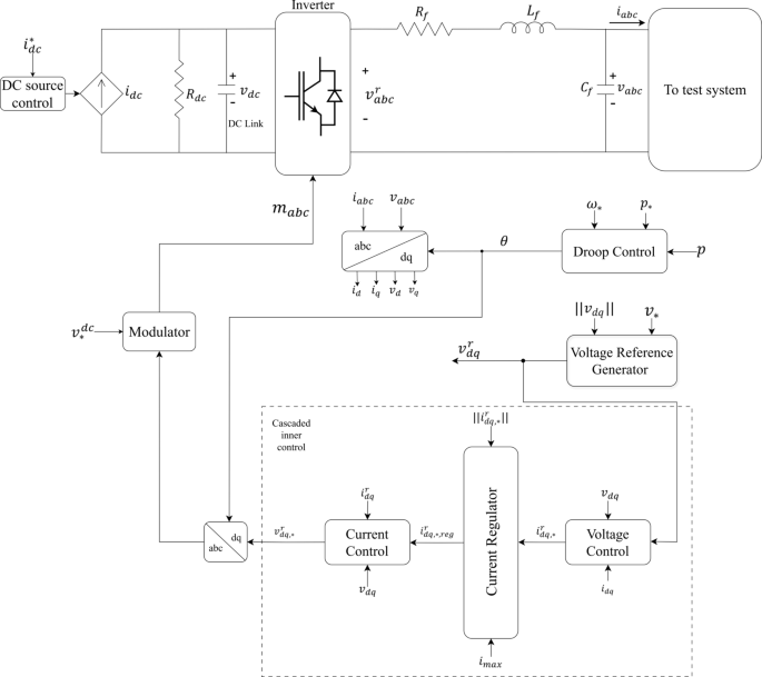
Hybrid-Compatible Grid-Forming inverters
Grid-forming inverters have appeared as a key technology in most modern power systems, especially when integrating renewable sources of energy while maintaining the stability of the grid. They are normally built to act like conventional synchronous generators to set voltage and frequency reference points for the grid. The main control strategy used for our HC-GFIs is the droop control method. This method keeps all inverters working independently from each other without fast communication links.
Control topology overview
The control strategy employed for HC-GFIs is designed as a multi-tiered hierarchical framework, structured to optimize dynamic performance and ensure robust grid interaction under varying system conditions. This architecture integrates several cascaded control layers, each responsible for a distinct operational function:
-
Droop Control: A decentralized strategy that emulates the inertial response of synchronous generators by modulating output frequency and voltage in proportion to active and reactive power exchange, thereby enabling autonomous frequency and voltage regulation.
-
Voltage Reference Generator: Computes dynamic voltage setpoints based on real-time PCC conditions, forming the outer loop that guides the downstream voltage regulation stage.
-
Voltage Control Loop: A high-bandwidth inner loop that maintains output voltage stability by minimizing tracking errors, ensuring fast and accurate transient response under disturbances.
-
Current Regulator: Applies nonlinear saturation logic to enforce inverter current limits, thus preventing overcurrent faults and protecting converter hardware.
-
Current Control Loop: Accurately tracks the regulated reference current, ensuring precise power delivery and smooth system dynamics.
-
Signal Modulation & DC Source Control: Translates dq-frame voltage references into PWM switching signals and regulates DC-side current through saturation control, ensuring safe and stable DC operation across varying load conditions.
Figure 1 provides a system-level schematic of the integrated control topology, highlighting the interconnections between the control layers. Functional diagrams in Figs. 2, 3, 4, 5 and 6 further elaborate on the droop controller, voltage and current loops, and DC-side regulation strategies.
Hierarchical multi-loop control topology of the proposed Hybrid-Compatible Grid-Forming Inverter (HC-GFI).
The control framework is fully modular and constructed using standard PI controllers with low-order filters and feedforward terms, making it suitable for real-time execution on embedded platforms such as DSPs or FPGAs.
Droop control
Droop control serves as a foundational grid-forming mechanism, enabling autonomous active power-sharing among inverters while maintaining system-wide frequency stability. By emulating the inherent characteristics of synchronous generators, this control method ensures that a decrease in system frequency results in an increased active power injection, thereby stabilizing the grid. The primary advantage of droop control is that it allows multiple inverters to operate in parallel, independently adjusting their output without the need for high-bandwidth communication links. Although no explicit synthetic inertia controller (e.g., virtual mass or (:domega:/dt)-based feedback) is implemented, the HC-GFIs achieve inertia-like performance through fast droop-based active power injection and high-speed control loops. The basic structure of the active power-frequency (P-f) droop control strategy is illustrated in Fig. 2.
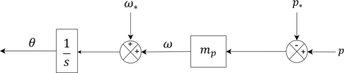
Active power–frequency droop control structure for primary frequency regulation.
The mathematical formulation of droop control is represented as follows:
$$:frac{d}{dt}left(theta:right)=omega:$$
(13)
$$:omega:={omega:}_{*}+{m}_{d}left({p}_{*}-pright)$$
(14)
The P-f droop mechanism enables the inverter to autonomously modulate its frequency in response to dynamic power imbalances, thereby facilitating decentralized frequency regulation. This feature is especially crucial in renewable-rich power networks, where the intermittent nature of solar PV and wind energy leads to continuous power fluctuations. By leveraging droop control, HC-GFIs actively contribute to frequency stabilization, ensuring that the system maintains a steady-state equilibrium despite fluctuating generation conditions.
Moreover, local frequency adaptation in droop-controlled inverters provides scalability and resilience, enabling distributed energy resources (DERs) to seamlessly integrate into larger grids. Unlike conventional centralized frequency control strategies, this approach allows for flexible and modular power system operation, significantly improving grid reliability under high renewable energy penetration. The proposed coordination scheme relies on decentralized droop-based control, enabling peer-to-peer operation of multiple HC-GFIs without any master-slave hierarchy or centralized synchronization, even during islanded conditions.
By incorporating these advanced droop control principles, HC-GFIs effectively replicate the behavior of conventional SGs, thus enhancing power-sharing dynamics and strengthening system inertia compensation mechanisms. The proposed implementation ensures seamless coordination between grid-forming inverters and synchronous generators, reinforcing frequency stability and dynamic response across hybrid power systems.
Voltage reference generator for cascaded control loop
The voltage reference generator is an essential component of the Hybrid-Compatible Grid-Forming Inverter (HC-GFI) control framework, operating as part of the outermost loop in the cascaded control hierarchy. It establishes a dynamic voltage reference that governs the inner voltage and current control loops, ensuring precise regulation and stability under varying grid conditions.
Maintaining a stable voltage profile at the Point of Common Coupling (PCC) is critical for grid synchronization and power-sharing accuracy, particularly in low-inertia power systems with high renewable penetration. The reference voltage is generated based on a Proportional-Integral (PI) control law, illustrated in Fig. 3 and formulated as:
$$:{v}_{dq}^{r}={k}_{p}^{d}left({v}_{*}-left|right|{v}_{dq}left|right|right)+{k}_{i}^{d}{int:}_{0}^{t}left({v}_{*}-left|right|{v}_{dq}left(tau:right)left|right|right)dtau:$$
(15)
where (:{v}_{dq}^{r}) is the reference voltage signal, (:{v}_{*}) is the desired setpoint, and (:left|right|{v}_{dq}left|right|) is the measured voltage magnitude. The proportional gain (:{k}_{p}^{d}) provides rapid correction, while the integral gain (:{k}_{i}^{d}) eliminates steady-state error, thereby improving voltage regulation performance.
Equation (15) ensures that voltage deviations are dynamically corrected, stabilizing the inverter output and enhancing grid robustness. The generated reference signal directly influences the inner voltage control loop, which adjusts the inverter’s output voltage to maintain grid stability. This framework is crucial for HC-GFIs to operate reliably in both grid-connected and islanded scenarios, reinforcing their adaptability and scalability in hybrid power networks.
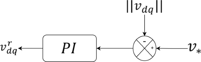
Voltage reference generation mechanism in the outer control loop.
Cascaded control loop
The cascaded control structure of Hybrid-Compatible Grid-Forming Inverters (HC-GFIs) is designed to enhance stability, voltage regulation, and current control in power systems. It decomposes control functionalities into three hierarchical loops:
-
1.
Voltage Control Loop – Regulates the inverter’s output voltage by generating appropriate current references.
-
2.
Current Regulator – Constrains reference current to prevent overcurrent conditions.
-
3.
Current Control Loop – Ensures precise tracking of the regulated current reference.
By segmenting the control process, the cascaded loop design enables improved dynamic response, better fault recovery, and enhanced power-sharing accuracy in both grid-connected and islanded scenarios.
Voltage control loop
The voltage control loop, illustrated in Fig. 4, serves as the primary regulation mechanism for inverter output voltage. It continuously monitors the deviation between the generated reference voltage (:{v}_{dq}^{r}) and the actual measured voltage (:{v}_{dq}), formulating an error signal as:
$$:{dot{zeta:}}_{dq}^{v}={v}_{dq}^{r}-{v}_{dq}$$
(16)
This voltage deviation is actively corrected using a Proportional-Integral (PI) controller, which plays a crucial role in ensuring voltage stabilization. The control law governing this process is expressed as:
$$:{i}_{dq,*}^{r}={k}_{p}^{v}{dot{zeta:}}_{dq}^{v}+{k}_{i}^{v}{zeta:}_{dq}^{v}+jomega:{C}_{f}{v}_{dq}+{i}_{dq}$$
(17)
where: (:{k}_{p}^{v}) and (:{k}_{i}^{v}) are the proportional and integral control gains, respectively, which adjust the response dynamics and ensure accurate voltage regulation. The error signal (:{dot{zeta:}}_{dq}^{v}) is continuously processed to minimize deviations between the reference and measured voltage. The feed-forward compensation terms (:jomega:{C}_{f}{v}_{dq}) and (:{i}_{dq}) account for capacitive filtering effects and real-time current feedback, improving the transient response of the control loop.
The output of the voltage control loop is a finely tuned current reference signal (:{i}_{dq,*}^{r}), which is subsequently fed into the current regulator for further refinement. This ensures that the inverter dynamically adapts to variations in grid conditions while maintaining stable and synchronized operation.
The role of Eq. (16) is to define the real-time error dynamics between the desired voltage and actual grid conditions, whereas Eq. (17) formulates the control response that corrects the deviation, ensuring that the inverter operates within nominal voltage levels. These equations collectively reinforce the robustness of the HC-GFI control scheme, particularly in mitigating voltage instability under dynamic grid conditions.
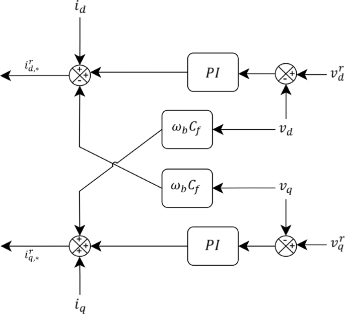
Voltage control loop for inner-layer regulation in the cascaded control framework.
Current regulator
The current regulator constitutes the second stage of the cascaded control structure, serving a critical role in protecting the inverter from excessive current drawing. This regulator ensures operational safety by dynamically adjusting the reference current signal to prevent the inverter from exceeding its maximum current rating, thereby safeguarding both power electronics and system stability.
To achieve this, a current-limiting algorithm is implemented, as defined in Eq. (18):
$$:{i}_{dq,*,reg}^{r}=left{begin{array}{c}{i}_{dq,*}^{r}:::::::::::::if::left|right|{i}_{dq,*}^{r}left|right|le:{i}_{max}\:sigma:{i}_{dq,*}^{r}::::::::::if::left|right|{i}_{dq,*}^{r}left|right|>{i}_{max}end{array}right.$$
(18)
where, (:{i}_{dq,*}^{r}) represents the unregulated current reference, derived from the voltage control loop. (:{i}_{max}) denotes the maximum allowable current limit of the inverter. The scaling factor (:sigma:) proportionally adjusts the reference signal when exceeding the current threshold, ensuring that the inverter never operates in an overcurrent condition.
This regulatory mechanism prevents excessive current spikes, particularly during transient disturbances such as fault conditions or sudden load changes. By enforcing strict current constraints, the regulator not only protects semiconductor switching devices from thermal stress but also maintains system reliability by preventing inadvertent inverter shutdowns due to overcurrent protection triggers.
The output of the current regulator, denoted as (:{i}_{dq,*,reg}^{r}), is subsequently fed into the current control loop, which further refines the signal for execution in the inverter’s switching mechanism. This ensures that only the appropriately regulated current reference is followed, maintaining safe, stable, and efficient operation of the HC-GFI system.
Current control loop
The current control loop serves as the final stage in the cascaded control architecture of the HC-GFI, ensuring that the actual output current precisely follows the reference current while maintaining power quality and system stability. This stage is responsible for ensuring that the inverter accurately tracks the prescribed current command without excessive deviation, which is critical in mitigating dynamic instabilities and ensuring robust power-sharing capabilities. The structure of this loop is shown in Fig. 5.
The current control loop operates based on real-time feedback measurements from current sensors that continuously monitor the inverter’s output current. The core function of this loop is to correct any discrepancies between the measured current and the reference current, ensuring that the system maintains the desired power flow and stability. The governing control equations for this stage are as follows:
$$:{dot{phi:}}_{dq}^{i}={i}_{dq,*,reg}^{r}-{i}_{dq}^{r}$$
(19)
$$:{v}_{dq,*}^{r}={k}_{p}^{i}{dot{phi:}}_{dq}^{i}+{k}_{i}^{i}{phi:}_{dq}^{i}+jomega:{L}_{f}{i}_{dq}^{r}+{v}_{dq}$$
(20)
The process begins by computing the current tracking error, which represents the deviation between the actual measured current (:{i}_{dq}^{r}:)and the regulated reference current (:{i}_{dq,*,reg}^{r}). This error signal is obtained from Eq. (19) and is represented by (:{dot{phi:}}_{dq}^{i}).
This signal is then processed through a PI controller, where the proportional gain (:{k}_{p}^{i}) ensures a fast dynamic response, and the integral gain (:{k}_{i}^{i}) eliminates steady-state errors, thereby enhancing accuracy in current regulation. The resulting control signal determines the reference voltage for the inverter. (:{L}_{f}) represents the output filter inductance, and (:{v}_{dq}:) denotes the grid voltage component. The last two terms in Eq. (20) incorporate feed-forward compensation, allowing the control system to dynamically counteract external disturbances and improve the inverter’s transient response.
By ensuring precise current tracking, this control loop significantly improves the robustness of HC-GFIs, enabling stable operation even under high penetration of renewable energy sources. The advanced feed-forward compensation mechanisms embedded in this control approach enhance the system’s ability to react swiftly to power fluctuations, ensuring seamless integration into modern power grids.
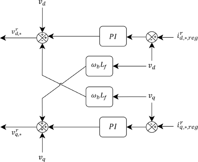
Current control loop structure including real-time current tracking and feed-forward compensation.
Signal modulator
The signal modulator operates as the final processing stage in the inverter’s control hierarchy, transforming the regulated voltage reference from the current control loop into actionable switching signals for the inverter. Following the completion of the cascaded control loop, where both voltage and current regulation are achieved, the modulation process ensures that the power electronic switches operate efficiently to synthesize the desired output voltage.
To convert the continuous voltage reference into discrete switching signals, Pulse-Width Modulation (PWM) is employed. The modulation scheme determines the switching patterns of the inverter’s semiconductor devices, enforcing the proper voltage and current waveforms at the inverter terminals. This modulation process is mathematically expressed as:
$$:{m}_{abc}=frac{2{v}_{abc,*}^{r}}{{v}_{*}^{dc}}$$
(21)
where, (:{m}_{abc}) represents the modulation index, dictating the switching duty cycles of the inverter, (:{v}_{abc,*}^{r}) is the three-phase reference voltage, generated as an output of the cascaded control system, and (:{v}_{*}^{dc}) is the DC-link voltage setpoint, regulating the inverter’s power flow.
The generated PWM signals control the switching states of the Hybrid-Compatible Grid-Forming Inverter (HC-GFI), ensuring that the output voltage and current precisely follow their reference values. This guarantees that the inverter maintains stable operation in both grid-connected and islanded modes, effectively supporting frequency regulation, voltage control, and power-sharing under dynamic grid conditions.
DC source control
The DC source control is a critical component in ensuring the stable operation of Hybrid-Compatible Grid-Forming Inverters (HC-GFIs), providing a regulated DC-link voltage that serves as the foundation for AC power synthesis. To achieve precise control, a saturation function is integrated into the DC source model, enhancing system reliability and operational safety by preventing overcurrent conditions. These safeguards are essential to protect both the inverter and the broader power network from excessive current transients that may arise due to load fluctuations, grid disturbances, or fault events.
Maintaining a fixed and regulated DC voltage is paramount for ensuring optimal inverter performance. Any deviation from the expected DC voltage can lead to distortions in the AC output waveform, affecting power quality and system stability. To regulate this parameter, the DC source employs a current-limiting mechanism, mathematically expressed in Eq. (22) as follows:
$$:{i}_{dc}=satleft({i}_{*}^{dc},{i}_{max}^{dc}right)=left{begin{array}{c}{i}_{*}^{dc}:::::::::::::::::::::if{::|i}_{*}^{dc}|<|{i}_{max}^{dc}|\:sgnleft({i}_{*}^{dc}right)::::::::::if::left|{i}_{*}^{dc}right|ge:left|{i}_{max}^{dc}right|end{array}right.$$
(22)
where: (:{i}_{dc}) represents the regulated DC current, (:{i}_{*}^{dc}) is the initial reference DC current, (:{i}_{max}^{dc}) denotes the maximum allowable DC current, and (:satleft(bullet:right)) is the saturation function, which constrains the current within its predefined operational limits. The implementation of Eq. (22) ensures that the system remains protected from overcurrent surges, which may arise due to sudden load variations or transient faults. This constraint is particularly essential in renewable-integrated power systems, where inverter-based resources (IBRs) operate under fluctuating power conditions.
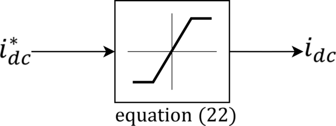
DC source regulation strategy incorporating saturation-based current limiting.
By embedding this current-limiting functionality within the control architecture, the need for additional hardware-based current limiters is eliminated, thereby reducing system complexity and improving overall efficiency. Moreover, as depicted in Fig. 6, the DC voltage control structure aligns with the broader cascaded control framework, reinforcing system resilience and adaptability in diverse operating conditions. The developed DC source control mechanism plays a pivotal role in ensuring that HC-GFIs remain within their designed operating limits, supporting the seamless integration of high-penetration renewable energy systems into the grid.