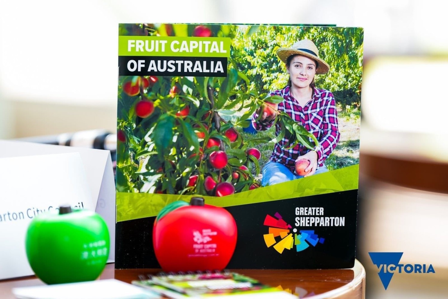
Palladium nanoparticles immobilized in SnFe2O4/SiO2/PM as efficient heterogeneous catalysts for the suzuki cross-coupling reaction

Preparation of SnFe2O4/SiO2/PM-Pd

The synthesis of SnFe2O4@SiO2 began with the production of SnFe2O4 following well-established protocols. Subsequently, 1 g of SnFe2O4@SiO2 was dispersed in 50 mL of toluene through 30 min of sonication. To this dispersion, 3 mL of 3-aminopropyltrimethoxysilane (APTES) was added, and the mixture underwent reflux for 24 h. The resulting SnFe2O4/SiO2/PM nanoparticles were purified by washing four times with ethanol, separated via magnetic decantation, and dried at 50 °C. In the next phase, 2 g of SnFe2O4/SiO2/PM was dispersed in 40 mL of toluene using a similar 30-minute sonication process, followed by the addition of 3 mmol of dicyclohexylcarbodiimide (PM). The mixture was then stirred under reflux conditions for another 24 h. The obtained nanoparticles were similarly washed multiple times with ethanol, magnetically separated, and dried at 60 °C. To graft Pd onto the heterogenized ligand, 1 g of SnFe2O4/SiO2/PM was reacted with 1.5 mmol of Pd(OAc)2 in CH3CN at room temperature for 24 h. The SnFe2O4/SiO2/PM-Pd nanoparticles were isolated by filtration, thoroughly cleaned with hot water and hot ethanol to remove any residual Pd, and subsequently dried at 60 °C. The overall procedure is represented schematically in Fig. 1.

Fig. 1

Synthesis of SnFe2O4/SiO2/PM-Pd.

General procedure for the suzuki reactions

A combination of aryl halide (1.0 mmol), phenylboronic acid (1.0 mmol), K2CO3 (1.5 mmol), and 30 mg of SnFe2O4/SiO2/PM-Pd catalyst was stirred in 3 mL of PEG-400 at 100 °C. The reaction progress was monitored using TLC, and upon completion of the cross-coupling reaction, hot distilled water was added to the mixture. The catalyst was then separated by filtration, and the product was further purified. Extraction of the desired product was carried out using a 1:1 mixture of water and ethyl acetate (Fig. 2).

Fig. 2
figure 2

SnFe2O4/SiO2/PM-Pd-catalysed Suzuki reaction.

Selected NMR data

4-methyl-1,1’-biphenyl (Table 2, Entry 3) (Figure S1)1:H NMR (400 MHz, DMSO): δH = 7.4 (m, 4 H), 7.1 (m, 5 H), 2.0 (s, 3 H), ppm.

3-methyl-1,1’-biphenyl (Table 2, Entry 9) (Figure S2)1:H NMR (400 MHz, DMSO): δH = 7.7 (m, 3 H), 7.5 (m, 2 H), 7.4 (m, 4 H), 1.9 (s, 3 H), ppm.

4-nitro-1,1’-biphenyl (Table 2, Entry 11) (Figure S3)1:H NMR (400 MHz, DMSO): δH = 8.2 (s, 1 H), 7.5 (s, 1 H), 7.3 (s, 3 H), 7.1 (s, 3 H), 7.0 (s, 1 H), ppm.

4-nitro-1,1’-biphenyl (Table 2, Entry 5) (Figure S4)1:H NMR (400 MHz, DMSO): δH = 8.1 (s, 2 H), 7.3 (m, 7 H), ppm.

1,1’-biphenyl (Table 2, Entry 12) (Figure S5)1:H NMR (400 MHz, DMSO): δH = 7.7 (s, 3 H), 7.4 (s, 4 H), 7.2 (s, 3 H), ppm.

1,1’-biphenyl (Table 2, Entry 10) (Figure S6)1:H NMR (400 MHz, DMSO): δH = 7.2 (m, 7 H), 6.9 (s, 3 H), ppm.

4-methoxy-1,1’-biphenyl (Table 2, Entry 13) (Figure S7)1:H NMR (400 MHz, DMSO): δH = 7.0 (m, 1 H), 6.9 (s, 3 H), 6.5 (m, 5 H), 4.0 (s, 3 H), ppm.

4-methoxy-1,1’-biphenyl (Table 2, Entry 4) (Figure S8)1:H NMR (400 MHz, DMSO): δH = 8.3 (m, 1 H), 7.9 (m, 1 H), 7.6 (s, 3 H), 7.1 (m, 4 H), 4.3 (s, 3 H), ppm.

3-methoxy-1,1’-biphenyl (Table 2, Entry 6) (Figure S9)1:H NMR (400 MHz, DMSO): δH = 8.2 (m, 2 H), 7.8 (m, 1 H), 7.6 (m, 3 H), 7.3 (m, 3 H), 3.7 (s, 3 H), ppm.

1,1’-Biphenyl (Table 2, Entry 1) (Figure S10)1:H NMR (400 MHz, DMSO): δH = 7.4 (m, 4 H), 7.0 (m, 6 H) ppm.

3-Nitro-1,1’-biphenyl (Table 2, Entry 2) (Figure S11)1:H NMR (400 MHz, DMSO): δH = 7.5 (m, 1 H), 7.4 (m, 2 H), 7.2 (m, 3 H), 7.1 (m, 3 H), ppm.

1-Phenylanthracene (Table 2, Entry 7) (Figure S12)1:H NMR (400 MHz, DMSO): δH = 7.6 (m, 2 H), 7.4 (m, 2 H), 7.0 (m, 3 H), 6.8 (m, 7 H), ppm.

1-([1,1’-Biphenyl]−4-yl)ethan-1-one (Table 2, Entry 8) (Figure S13)1:H NMR (400 MHz, DMSO): δH = 7.0 (m, 5 H), 6.7 (m, 4 H), ppm.

Catalyst characterizations

To verify the successful functionalization of SnFe2O4/SiO2/PM-Pd magnetic nanoparticles (MNPs), FT-IR spectroscopy was conducted using the KBr pellet method (Fig. 3). In Fig. 3(a), vibrational bands at 740 and 580 cm⁻¹, observed across all FT-IR spectra, correspond to the stretching vibrations of the Sn-O bond. Additionally, peaks near 3490 cm⁻¹ are attributed to hydroxyl groups located on the surface of the magnetite. Figures 3(b–c) reveal peaks at 1064 cm⁻¹ and within the range of 2919–3029 cm⁻¹, which can be attributed to the ν(Si─O) and ν(C─H) vibrational modes, respectively; these specific bands are absent in the magnetite spectrum. The presence of these vibrations indicates the successful incorporation of SiO2 and APTES onto the SnFe2O4 nanoparticles. The immobilization of the PM group onto SnFe2O4/SiO2 is confirmed by the appearance of a C═N vibrational band at approximately 1630 cm⁻¹, along with a C─H vibrational band near 1418 cm⁻¹ (Fig. 3d). Furthermore, in the spectrum of SnFe2O4/SiO2/PM-Pd (Fig. 3e), the downward shift of the C═N vibrational band to a lower frequency at approximately 1466 cm⁻¹ provides evidence for the successful formation of the Pd complex on the surface of the functionalized SnFe2O4 nanoparticles37,38,39,40.

Fig. 3
figure 3

Comparative study of FT-IR spectra of (a) SnFe2O4, (b) SnFe2O4/SiO2, (c) SnFe2O4/SiO2/APTES, (d) SnFe2O4/SiO2/PM, (e) SnFe2O4/SiO2/PM-Pd.

The crystalline phase of SnFe2O4/SiO2/PM-Pd MNPs was analyzed using XRD. As depicted in Fig. 2, the material exhibited seven distinct and well-defined peaks at 2θ values of 18.3°, 30.4°, 36.7°, 37.4°, 43.1°, 54.8°, 56.4°, 63.5°, 72.5°, and 75.3°. These peaks corresponded to the (111), (220), (311), (222), (400), (422), (511), (200), (620), and (533) planes, respectively, and aligned closely with previously reported XRD patterns for SnFe2O4 MNPs. This confirms that the tubular structure of SnFe2O4 remains intact following its functionalization and stabilization within the silica sulfuric acid shell. Additionally, the analysis highlighted a noisy background caused by the amorphous dried PM-Pd shells, as illustrated in Fig. 441,42..

Fig. 4
figure 4

XRD spectrum of SnFe2O4/SiO2/PM-Pd.

The TGA curve of SnFe2O4/SiO2/PM-Pd demonstrates three distinct stages of mass loss. The initial stage, involving a 7% mass reduction at temperatures below 200 °C, is attributed to the evaporation of adsorbed organic solvents. As illustrated in Fig. 5, the second stage occurs between 200 and 600 °C, during which the removal of organic components results in a 20% mass loss. Based on this data, it can be concluded that the synthesized catalyst remains thermally stable up to 600 °C without degradation. Lastly, a third stage of mass loss, approximately 3.27%, is observed at temperatures exceeding 600 °C. This is associated with the condensation of silanol groups, leading to the loss of OH groups. These findings confirm the successful integration of the PM-Pd complex into the SnFe2O4 framework.

Fig. 5
figure 5

TGA curve of SnFe2O4/SiO2/PM-Pd.

To confirm the presence of palladium metal on the surface of functionalized boehmite, the EDS technique was employed. The resulting EDS spectrum of SnFe2O4/SiO2/PM-Pd nanoparticles is depicted in Fig. 6. The spectrum clearly indicates the presence of Sn, Si, C, N, O, and Fe, along with Pd species in the SnFe2O4/SiO2/PM-Pd composition. These results from the EDS analysis enhance the understanding of the catalyst’s structural makeup and offer potential insights into its catalytic performance. Further exploration of the relationship between elemental distribution and catalytic properties could provide critical guidance for refining catalyst design and improving performance in future research endeavors.

Fig. 6
figure 6

EDS analysis of SnFe2O4/SiO2/PM-Pd.

A scanning electron microscope (SEM) was employed to analyze the size and morphology of SnFe2O4/SiO2/PM-Pd particles (Fig. 7). The SEM analysis indicated that these particles possess uniform spherical shapes, with diameters ranging from 20 to 60 nm. Furthermore, the images revealed particle agglomeration, likely caused by the magnetic properties of the nanoparticles.

Fig. 7
figure 7

SEM images of SnFe2O4/SiO2/PM-Pd.

Figure 8 presents the XPS spectrum of the synthesized SnFe2O4/SiO2/PM-Pd catalyst, showcasing distinct peaks corresponding to Si, Sn, O, C, N, Fe, and Pd. These elemental contributions are further detailed in Fig. 8a. An in-depth XPS analysis of palladium is provided in Fig. 8b, which identifies its oxidation state through characteristic binding energy peaks at 331.2 eV and 346.4 eV, attributed to Pd 3d5/2 and Pd 3d3/2, respectively. This thorough examination confirms the structural composition of the SnFe2O4/SiO2/PM-Pd catalyst43,44,45,46,47,48..

Fig. 8
figure 8

XPS spectra of SnFe2O4/SiO2/PM-Pd.

Figure 9 presents TEM images of the SnFe2O4/SiO2/PM-Pd magnetic nanoparticles (MNPs). The images reveal nearly spherical layers, with darker regions likely corresponding to the SnFe2O4 nanoparticles forming the core. Encasing these core nanoparticles, a brighter layer is visible, representing a distinct coating. This outer layer is likely evidence of the successful immobilization of the palladium (Pd) complex on the surface of the titanium ferrite nanoparticles. The contrast between the darker core and the brighter coating underscores the composite structure of the material, clearly delineating its core and functionalized outer layer as shown in Fig. 9.

Fig. 9
figure 9

TEM images of SnFe2O4/SiO2/PM-Pd.

The ICP method was employed to determine Palladium concentrations in the original catalyst and to evaluate Pd leaching following recycling. The findings revealed that the Pd contents in the fresh and recycled catalysts were 2.3 × 10⁻³ and 2.2 × 10⁻³ mol g⁻¹, respectively. This demonstrates negligible Pd leaching from the SnFe₂O₄/SiO₂/PM-Pd structure.

The magnetization of SnFe2O4 and SnFe2O4/SiO2/PM-Pd was examined at room temperature using a VSM, as illustrated in Fig. 10. The resulting magnetization curves indicated saturation magnetization values of 59 emu/g for SnFe2O4 and 41 emu/g for SnFe2O4/SiO2/PM-Pd. The decrease in saturation magnetization observed in the prepared catalyst is linked to the stabilization of the PM-Pd complex on the surface of SnFe2O4.

Fig. 10
figure 10

VSM curves of (a) SnFe2O4 (b) SnFe2O4/SiO2/PM-Pd.

Catalytic study

After characterizing SnFe2O4/SiO2/PM-Pd, its catalytic efficiency for synthesizing biphenyl byproducts was analyzed using the Suzuki–Miyaura coupling reaction. Reaction parameters were initially optimized by varying the solvent, base, and catalyst concentrations in a model reaction between phenylboronic acid and iodobenzene, as outlined in Table 1. A blank experiment conducted without the catalyst in PEG solvent at 100 °C showed no reaction progress, even after an extended duration (Table 1, entry 1). Additionally, when the catalyst was removed midway through the reaction at 50% conversion, no further transformation occurred, reinforcing its critical role in driving the reaction forward. This underscores the importance of the SnFe2O4/SiO2/PM-Pd catalyst in facilitating the Suzuki–Miyaura coupling process. Table 1 (entry 4) demonstrates that 30 mg of SnFe2O4/SiO2/PM-Pd is sufficient to complete the reaction within 20 min with 1 mmol of iodobenzene in PEG at 100 °C. The next phase involved evaluating the effect of various solvents, including H2O, EtOH, PEG-400, DMF, and toluene, under identical conditions with 30 mg of catalyst. These tests revealed that environmentally friendly PEG was superior to all other solvents. To determine the impact of different bases on the reaction rate, accessible inorganic bases such as K2CO3, NaOH, and KOH were tested. Among these, K2CO3 emerged as the most effective base (Table 1), likely due to its higher solubility in PEG-400 medium. From both economic and reaction optimization perspectives, K2CO3 was validated as the most suitable choice. Further optimization involved varying the molar ratio of K2CO3. It was observed that reducing the amount to 1 mmol led to a slower reaction rate, whereas increasing it to 1.7 mmol provided no additional benefit (Table 1). These findings highlight the importance of fine-tuning reaction parameters for optimal efficiency.

Table 1 Optimization of the reaction conditions for the coupling reaction of Phenylboronic acid with iodobenzene.

After optimizing all reaction conditions, the coupling of phenylboronic acid with various aryl halides (I, Br, and Cl) was carried out using 30 mg of SnFe2O4/SiO2/PM-Pd under ultrasonication at the established optimal conditions. The results, summarized in Table 2, highlight the efficiency of the process in facilitating reactions between phenyl chlorides, bromides, and iodides with phenylboronic acid to produce the desired products. As shown in Table 2, the catalyzed reactions involving aryl halides with either electron-donating or electron-withdrawing functional groups consistently achieved high yields of the corresponding products. It is worth noting that while the process delivers high yields across all evaluated reactions, the coupling of aryl chlorides with phenylboronic acid requires a longer reaction time to achieve moderate product yields compared to the coupling reactions of aryl bromides and iodides.

Table 2 Catalytic coupling reaction of various Aryl halides with Phenylboronic acid.

A proposed mechanism for the anthrax reaction involves a series of key steps. First, aryl halides engage in oxidative addition to the Pd complex, resulting in the formation of intermediate 1. This is followed by intermediate 2 undergoing transmetallation, which leads to the production of intermediate 3. Lastly, reductive elimination takes place, restoring the SnFe2O4/SiO2/PM-Pd species and yielding the target product as outlined in Fig. 11.

Fig. 11
figure 11

Possible mechanism for Suzuki reaction.

Hot filtration

The hot filtration and leaching tests were employed to verify the heterogeneous nature of the synthesized material, independent of whether any catalyst particles were present in the filtrate solution. During the Suzuki–Miyaura cross-coupling reaction, the nanocatalyst was utilized for 10 min under optimal conditions, after which the reaction mixture was split into two portions. The catalyst was extracted from one portion using a magnetic field, and both portions were then allowed to react for an additional 10 min. It was observed that no conversion occurred in the catalyst-free environment, while the reaction in the other portion proceeded to completion, as detailed in the Supporting Information. These results strongly indicate that minimal to no Pd leaching occurred within the reaction mixture, thus confirming its genuine heterogeneity.

Continue Reading