Magma stages and degassing mechanisms
For the magma part of the model, we adopted the description of different magma stages during cooling from studies on pore-scale processes20,23,24 based on crystal volume fractions (CVFs) and volatile volume fractions (VVFs):
-
Suspension (CVF < 0.4): in this state of low-crystallinity mobile magma, volatiles can exsolve when the melt reaches water saturation, but the volatile bubbles remain in suspension due to convection, which exceeds bubble ascent velocities.
-
Intermediate-crystallinity mush (0.4 < CVF < 0.7): in this state, the fluid behavior depends on whether the VVF exceeds a percolation threshold (PT) for the formation of tube-flow channels:
-
Impermeable mush (VVF < PT): magma is in a mush state but the volatiles cannot form tube-flow channels required for fluid migration. If the magma is still mobile at CVF < 0.5, the trapped volatile bubbles are still transported by magma convection as in the suspension state.
-
Tube-flow mush (VVF < PT): in this state, tube-flow channels can develop and allow for rapid degassing. In the model, we assume that the amount of volatiles above the PT can flow through the permeable tube-flow mush to the cupola region and be released to the host rock.
-
-
Fracturable mush (CVF < 0.7): in this state of highly crystalline magma, volatile release occurs only via capillary fracturing under overpressure. In the model, we assume that all volatiles can eventually be released to the host rock, by gradually lowering the PT to a value of 0.0 at the solidus (CVF = 1.0).
In transient simulations, several of these magma stages can occur at the same time in different parts of the reservoir. Magma evolution and volatile degassing during cooling and crystallization is strongly influenced by convection, which we assume to cease at crystal-dominated conditions. In the degassing part of the model, we therefore first distinguish between different degassing stages during homogeneous and radial cooling.
-
Homogeneous cooling occurs before crystal lockup (CVF < 0.5) due to advective heat redistribution by magma convection. In combination with the constraint that outgassing at intermediate crystallinities is limited to tube-flow mush, we further subdivide this stage by different fluid outgassing mechanisms:
-
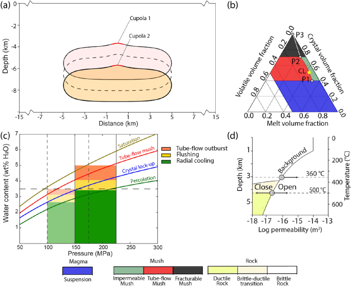
Tube-flow outburst is a short-lived, high-flux degassing event, occurring in water-rich magmas during the transition from suspension to tube-flow mush at the cupola region when VVF exceeds the percolation threshold at CVF = 0.4. At the same time, the magma reservoir at greater depth can be in a state of impermeable mush due to the pressure-dependence of water saturation (Fig. 1c). All the exsolved fluids above the percolation threshold (P1 in Fig. 1b) from the entire magma reservoir are now assumed to flow towards the cupola and are released to the host rock.
-
Flushing follows the tube-flow outburst event and occurs before lock-up in the state of intermediate crystallinity by ongoing magma convection. The model assumes that the mush is still mobile at 0.4 < CVF < 0.5. As a consequence, the cupola region is kept in a state of tube-flow mush, where fluids can form tube-flow channels and physically separate from the mush. Most of the magma volume remains in a state of impermeable mush but exsolved volatiles can be transported (“flushed”) with the convecting magma to the cupola region where the volatiles in excess of the percolation threshold are released to the host rock.
-
-
Radial cooling occurs after crystal lock-up (CVF < 0.5), when the magma body cools conductively from the outside inward with fluid transfer dominated by capillary fracturing. During this stage, the system forms concentric rings of tube-flow and fracturable mush. Exsolved fluids are assumed to use this dynamically increased permeability to flow to the cupola zone and be released to the host rock. A numerical representation of that process has been described by Ref19.
Governing equations and initial conditions
The coupled magmatic-hydrothermal model simultaneously solves for magma convection within the reservoir (Navier-Stokes equations), fluid flow in the host rock (Darcy’s law), heat conduction and latent heat release22.
Magma convection is governed by an implementation of the Navier-Stokes equations with the momentum conservation equation:
$$begin{aligned} rho _{0} frac{partial u}{partial t}=mu nabla ^{2} u-nabla P-rho _{0} u cdot nabla u-rho g end{aligned}$$
(1)
and the continuity equation for incompressible magma:
$$begin{aligned} nabla cdot u=0 end{aligned}$$
(2)
Conservation of energy within the magma reservoir is obtained by solving:
$$begin{aligned} frac{partial T}{partial t}=u cdot nabla T+nabla cdot frac{K}{rho _{0} c_{p}} nabla T-frac{L}{c_{p}} frac{partial F}{partial t} end{aligned}$$
(3)
with temperature T, specific heat capacity (c_{p}=880~textrm{J}~textrm{kg}^{-1 circ }textrm{C}^{-1}), latent heat of crystallization (L=3.5 cdot 10^{5}~textrm{J} ~textrm{kg}^{-1}), thermal conductivity (K=2~textrm{W}~textrm{m}^{-1 circ }textrm{C}^{-1}), and melt fraction F.
In the permeable host rock, Darcy flow of multi-phase compressible saline fluids ((H_{2}O + NaCl)) is calculated as:
$$begin{aligned} v_{i}=-k frac{k_{r, i}}{mu _{i}}left( nabla p-rho _{i} gright) , quad i=l, v end{aligned}$$
(4)
where k is the bulk rock permeability, (k_{r}) the relative permeability of phase (i, mu _{i}) the dynamic viscosity, p fluid pressure, and (rho _{i}) the density of phase i. For the mobile phases, a linear relative permeability model is applied with (k_{r v}+k_{r l}=1-S_{h}), the saturation of an immobile solid halite phase (S_{h}), the residual saturation (R_{l}=0.3left( 1-S_{h}right)) for the liquid phase and (R_{v}=0.0) for the vapor phase.
Conservation of fluid mass, salt mass and energy are calculated as:
$$begin{aligned} & frac{partial left( phi left( S_{l} rho _{l}+S_{v} rho _{v}+S_{h} rho _{h}right) right) }{partial t}=-nabla left( v rho _{l}right) -nabla left( v_{v} rho _{v}right) +Q_{H_{2} O+N a C l} end{aligned}$$
(5)
$$begin{aligned} & frac{partial left( phi left( S_{l} rho _{l} X_{l}+S_{v} rho _{l} X_{v}+S_{h} rho _{h}right) right) }{partial t}=-nabla left( v_{l} rho _{l} X_{l}right) -nabla left( v_{v} rho _{v} X_{v}right) +Q_{N a C l} end{aligned}$$
(6)
$$begin{aligned} & frac{partial left( (1-phi ) rho _{r} h_{r}+phi left( S_{l} rho _{l} h_{l}+S_{v} rho _{v} h_{v}+S_{h} rho _{h} h_{h}right) right) }{partial t}= nonumber \ & quad nabla (K nabla T)-nabla left( v_{l} rho _{l} h_{l}right) -nabla left( v_{v} rho _{v} h_{v}right) +Q_{e}. end{aligned}$$
(7)
with the porosity (phi), the mass fraction of (textrm{NaCl}) (X_{i}), the specific enthalpy (h_{i}), the source terms (Q_{textrm{H}_{2} textrm{O}+textrm{NaCl}}, Q_{textrm{NaCl}}) and (Q_{e}), and the subscript r for the rock.
The numerical approaches for fluid and magma flow have both been benchmarked in previous studies22,34. The calculation of dynamic magma, fluid and rock properties follows the descriptions in Ref21. The energy conserving equations (Eqs. 3 and 7) are coupled through the respective heat conduction terms in dependence on the thermal conductivity K, which controls the heat transfer from the magma reservoir to the host rock, forming a conduction-dominated zone with no magma and fluid flow at temperatures between crystal lock-up at CVF = 0.5 and the brittle-ductile transition, where permeability is gradually increased (Fig. 1d). Due to the non-linear nature of dynamic magma viscosity on the one side and dynamic permeability on the other side, the evolution of this zone is affected by the mesh resolution. Vigorous convection in low-viscosity, low-crystallinity magmas can lead to highly transient, thin thermal plumes that would require very fine mesh resolutions. For the present simulations, we use a mesh resolution that is coarse enough to be computationally feasible and fine enough to reduce mesh effects and capture the main effect of heat transfer by magma flow from the center to the rim of the reservoir at intermediate-crystallinity conditions22.
To investigate the interplay of coupled processes controlled by non-linear properties of melts, rocks and fluids, we use a generic set-up including a stylized magma reservoir with a total volume of about 50 (mathrm {~km}^{3}), commonly assumed to be the minimum size for porphyry copper systems. Previous simulations resolving incremental sill emplacements show that such reservoirs can be built up with magma injection rates on the order of (10^{-2} mathrm {~km}^{3} / textrm{yr})13. For this study, the simulations focus on volatile degassing which starts at intermediate crystallinities of CVF = 0.4. To obtain realistic initial boundary conditions for this stage of magma degassing, the model first calculates an incubation phase, where conductive heat transfer from an initially (970;^{circ }textrm{C}) hot magma reservoir to the host rock generates a low-permeability conductive boundary layer around the intrusion. During this incubation phase, which lasts about 10-15 kyrs depending on the intrusion depth (Fig. 2), magma convection thermally homogenizes the reservoir at CVF < 0.4. The subsequent degassing phase from a mush state (CVF < 0.4) now starts at conditions with a conductive boundary layer around the reservoir of 1-2 km thickness (see (400;^{circ }textrm{C}) isotherm Fig. 2). At these conditions of intermediate crystallinities (0.4 < CVF < 0.5), magma viscosity has already increased substantially, leading to less vigorous convection as compared to the incubation phase.
Fluid release from tube-flow and fracturable mush
We calculate crystallization as (mathrm {X = 1 – left( frac{T – T_{sol}}{T_{liq} – T_{sol}}right) }^{b}) with a temperature for liquidus and solidus of (mathrm {T_{liq}} = 1000;^{circ }textrm{C}) and (mathrm {T_{sol}} = 700;^{circ }textrm{C}), respectively, and b = 0.4. For the degassing model, we further take the respective densities of melt, crystals and volatiles into account21, which leads to varying temperatures for the transitions between the different magma stages in dependence on pressure and water contents.
The ternary diagram for magma evolution (Fig. 1b) defines sharp transitions between suspension (blue), tube-flow mush (red), impermeable mush (green) and fracturable mush (black). These transitions lead to strong variations in fluid release rates when large parts of the modelling domain reach the respective thresholds at CVFs of 0.4 and 0.7.
Fluids can first be released from the field of tube-flow mush (red), with volatile volume fractions (VVFs) above the percolation threshold between P1 and P2. The self-organization of magma reservoirs with high water contents into tube-flow outburst events (direct transition from blue to red field in Fig. 1b at CVF = 0.4) provides a challenge for the dynamic permeability model (Fig. 1d). The high fluid injection rates lead to extreme increases in fluid pressure at the cupola region, in particular if 3D fluid focusing effects are considered.
The relative extent into the third dimension of the domain is given by a user-defined scaling parameter, which we set to (f_{3 D}=0.25) for this study. With this scaling factor, we control the size of the magma and the domain in a three-dimensional geometry within a two-dimensional simulation domain. For a radial factor (f_{3 D}=0.25), the domain with 30 km width extends 7.5 km in the unresolved 3rd dimension. With this scaling, the (10-textrm{km}) wide reservoirs of Fig. 1a have an elongated shape with an extent of 2.5 km in the non-resolved third dimension, resulting in a total volume of ca. 50 (textrm{km}^{3}) of the intrusion. Volatile degassing is prescribed to occur across the cupola region with a radius (r=300 mathrm {~m}) and an area (A_{text{ cupola } }=pi r^{2} f_{3 D})16,21.
The model imposes a maximum permeability of (k_{max }=10^{-13} mathrm {~m}^{2}), which is representative for a disturbed crust at several km depth35 and restricts the rates at which magmatic fluids can be released from the magma reservoir. Using the mass balance equation, we can estimate the maximum injection rate (Q_{max }) that can maintain a fluid pressure gradient (nabla p_{text{ fluid } }) equal to the lithostatic pressure gradient (nabla p_{text{ lithosatic } }=rho _{text{ rock } } cdot g) as:
$$begin{aligned} Q_{max }= & v_{max } cdot rho _{text {fluid}} cdot A_{text {cupola}} end{aligned}$$
(8)
$$begin{aligned} v_{max }= & frac{k_{max }}{mu } cdot left( nabla P – rho _{text {fluid}} cdot gright) end{aligned}$$
(9)
$$begin{aligned} Q_{max }= & k_{max } frac{rho _{text {fluid}}}{mu _{text {fluid}}} cdot left( rho _{text {rock}} – rho _{text {fluid}}right) cdot g cdot A_{text {cupola}} end{aligned}$$
(10)
Fluid density and viscosity are calculated for TPX-conditions of the injected fluid at the cupola36,37. Furthermore, the model ensures that volatile release can only start when the cupola region has reached a mush state, even if fluid migration has already started at deeper levels within the reservoir. This approach reflects real-world conditions where magmatic fluids are transported within the domain of tube-flow mush towards the cupola and stored in a bubbly foam layer within the magma chamber. Gradual fluid release acts as a buffer, smoothing outburst durations and extending volatile release.
As a second modification to further mitigate the mesh-dependent fluctuations in outgassing behavior at CVF (=0.7) observed in previous modelling studies21, which are related to the sharp transition from tube-flow (red) to fracturable mush (black), we now gradually lower the percolation threshold for fluid release from fracturable mush during further crystallization from P2 to P3.
Parameterization of permeability increase during brecciation
After fluid release, the host rock responds with dynamic permeability variations due to hydraulic fracturing according to Fig. 1d (for details see ref38). The dynamic permeability model relies on an ad-hoc parameterization of incremental permeability increase at fluid pressures (p_{text{ fluid } }) exceeding a calculated failure criterion (p_{text{ fail } })16. In the original model, permeability increases used a dependence on (left( frac{p_{text{ fluid } }}{p_{text{ fail } }}right) ^{2}). To allow faster permeability generation by hydrothermal brecciation, we modified this parametrization to a log-quadratic dependence with
$$begin{aligned} log left( k_{t+d t}right) =log left( k_{t}right) +f_{k p c}left( left( frac{p_{text{ fluid } }}{p_{text{ fail } }}right) ^{2}-1right) end{aligned}$$
(12)
This parameterization extends the relationship in Figure 9 of ref39 where an increase in pore fluid factor translates into an increase in log permeability to hydraulic fracturing at (p_{text{ fluid } }>p_{text{ fail } }) and can now be modified by the user with a conversion factor for permeability-pore-fluid-coupling (f_{k p c}left( textrm{m}^{2}right)).
The parmaterization requires that fluid pressures in access of the failure criterion generate permeability and a steep fluid pressure gradient to allow magmatic volatiles to ascend. As a post-processing step, we calculate the amount of additional porosity this excess pressure would generate, which provides a measure for the degree of brecciation40.
The dynamic permeability model assumes that the brittle crust is near-critically stressed with hydraulic fracturing occurring at near-hydrostatic fluid pressures. Differential stress is gradually reduced along the brittle-ductile transition, leading to hydraulic fracturing of nominally ductile rock at fluid pressures with near-lithostatic values. In natural systems, magma emplacements may influence the stress field around the reservoir, which could affect fracturing and fluid focusing ore even dike injections and volcanic eruptions. Capturing such mechanisms will require the implementation of additional processes into the coupled model. However, we expect that the first-order processes studied in this contribution will still be valid in more complex systems.
Fluid-melt partitioning of copper and salt
To study the interconnected behavior of outgassing of magmatic volatiles and chemical enrichment of ore elements during crystallization, we added functionality for fluid-melt partitioning of metals and salt. We use constant distribution coefficients to study the fate of ”enthusiastically fluid-loving” ((textrm{D}=50)) and ”reluctantly fluid-loving” ((textrm{D}=5)) chemical components9. As a consequence, (textrm{D}=50) leads to early copper partitioning into the fluid, while (D=5) reflects enrichment later in the crystallization process. For simplicity, we assume that Cu and NaCl have the same D values, which also leads to varying salinities of the outgassing fluid and can affect the evolution of the hydrothermal system.
Applying constant values for the distribution coefficient D is a simplification intended to capture the first-order control of fluid-melt partitioning during the evolution from early to late degassing following the schematic example9. Distribution coefficients can vary with pressure, temperature and melt composition9 and can be particularly redox-sensitive in the case of copper7. Capturing the complexity of these thermodynamic interactions is beyond the scope of this study, but could be incorporated into the model with further developments.
Copper precipitation from these released saline, metal-rich magmatic fluids in the hydrothermal system is modelled to occur between 350 and (450 ^{circ }textrm{C})16, which is typically inferred for mineralization in porphyry copper deposits.
This temperature window for Cu mineralization also generally agrees with numerical simulations using proxies for temperature- and salinity-dependent solubilities of Cu17,18. An accurate description of all relevant chemical fluid-rock reactions will require to incorporate full reactive transport modeling and to develop an internally consistent thermodynamic database for the relevant ranges in temperature, pressure and composition.