PHILADELPHIA – Lehigh’s women’s track and field team traveled to the University of Pennsylvania for their first away meet of the season, the Penn Select meet.
The field events started the competition, where the Mountain Hawks had a few top…
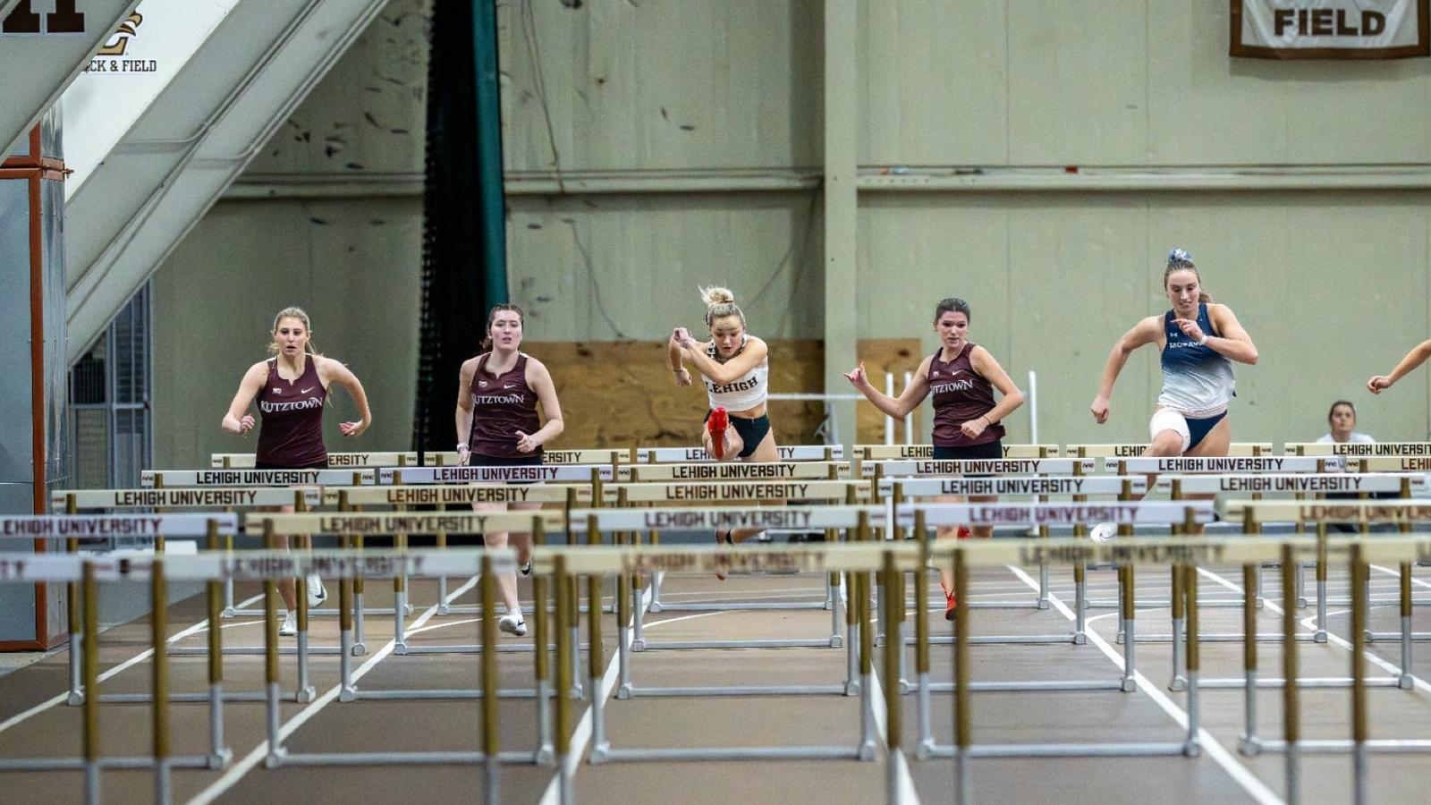
The field events started the competition, where the Mountain Hawks had a few top…
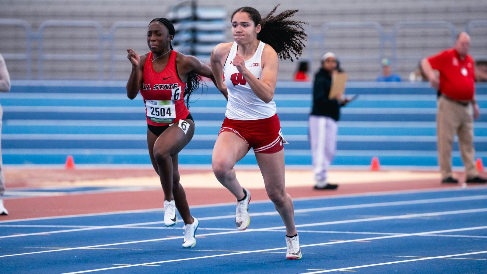
CHICAGO – The Wisconsin women’s track and field squad delivered a commanding performance at the Badger Midwest Invite, sweeping the weight throw and collecting five event titles.
Senior Rachel Robinson ran her personal best in the 60 meter…